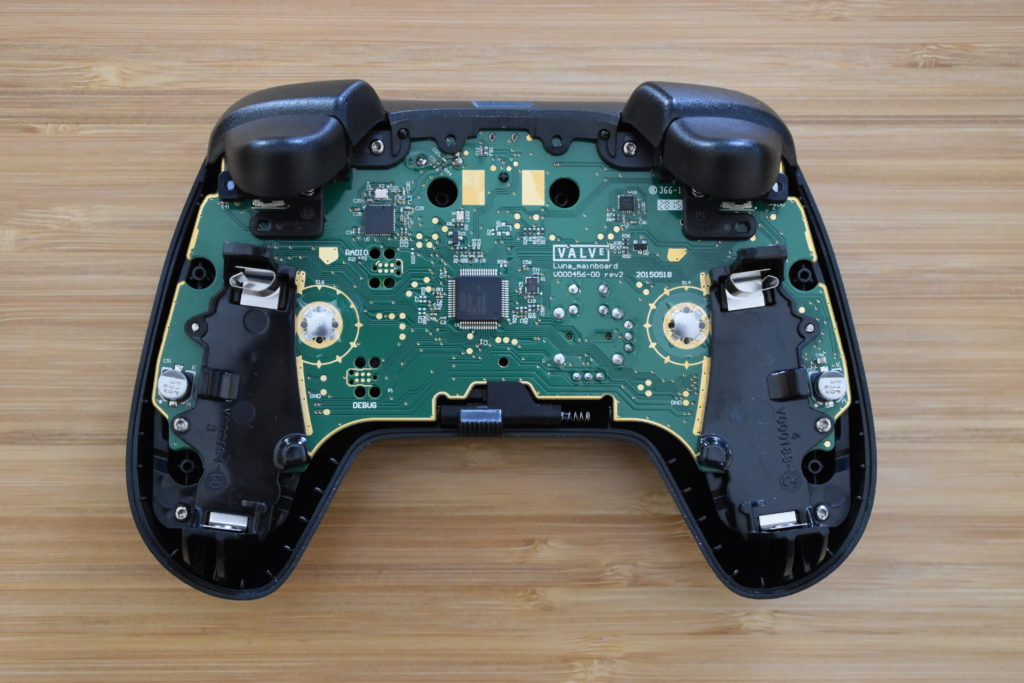
Torx drivers came in and I was able to remove the back plate of my Steam Controller. I took some pictures because the iFixit pictures had the outline around the MCUs.
I pulled out my little multimeter and switched to continuity checker. I also used Krita to trace the lines in individual layers to keep track of what I found. I only got through the connection between the MCUs. I found 5 pins connected from the nrf51822 and the LPC11U37F. SWDIO/nReset and SWCLK are interesting. I understand keeping nRESET attached to allow the 11U37 to reset the 51822, but the SWCLK is a little surprising. It makes me think that the 11U37 may be able to program the 51822 directly. It wouldn’t be for programming at manufacture because both the debug headers are available. This could also potentially be used to allow the 11U37 expose a USB endpoint that acts like a debugger so a developer could load/debug code without a torn-down unit. I can definitely see that as a cool use.
I also found two pins that go from the RX/TX UART lines on the 11U37 to the 51822. That leads me to assume they are communicating over UART. This isn’t too surprising. I was assuming either SPI or UART before I opened up the controller. The 51822 does support DMA for the SPI slave so it can receive data without waking the CPU. SPI would have required at least one extra pin for CLK and probably another for chip select. It would probably need another to also allow for the 51822 to request servicing by the 11U37. An extra 2-3 pins may have been too much given that pretty much all the pins on the 11U37 are already in use. It also may have been very difficult for routing. From what I can tell, it’s a two layer board and pretty dense around the 11U37. I think for an application like this, I would have looked at SPI pretty closely. It shifts the design from a peer-to-peer protocol to a master-slave approach. That can be really nice for code architecture because it becomes just another peripheral. Of course, this is me saying this without any understanding of how the code is structured.
And that leaves one more pin. I’ve got no idea and probably won’t be able to figure it out until I capture some signal traces with a logic analyzer. Some completely random guesses, heart beat to the 11U37, interrupt if the UART is a command-reply protocol, or maybe some other state pin like currently connected.

